Layup Options for Cooling Water Systems
January 6, 2022
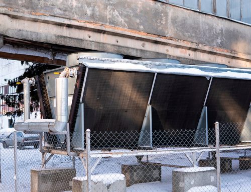
Cooling towers are an integral part of any cooling system and must work within the design specification for the system to properly function. A cooling tower operating outside its specifications will increase the overall costs of operations due to higher energy and water usage. When it comes time to lay the system up, much thought and consideration is given to protecting the water side of the system (i.e., piping, pumps, valves, heat exchangers, and other associated equipment). However, little attention is paid to exterior surfaces of the equipment, associated control panels, and the cooling tower structure. Excess corrosion on any of these surfaces over time can lead to system failure and expensive non-budgeted repairs or equipment replacement.
This guide outlines strategies to provide an integrated approach to protect the entire system, not just water side components.
 The cooling tower structure consists of the following components:
- Fan Blades – Fiberglass reinforced polyester (FRP), aluminum, galvanized steel
- Rotating Shaft – Steel
- Motors
- Louvers – Typically FPR but can be galvanized steel or stainless steel
- Fill – Plastic sheet
- Structure – Normally galvanized steel, but can be stainless steel or fiberglass reinforced polyester (FRP)
- Drift Eliminator – Polypropylene material filled with carbon black
- Cold Water Basin – Concrete, galvanized, FRP, or stainless steel
- Sump – Same material as cold-water basin; receives water from the basin
- Hinged Access Door – Steel
- Walkways and Ladders – Galvanized steel
- Casing – Fiberglass
- Inlet Header
- Fan Cylinder – Fiberglass reinforced plastic (FRP)
- Railing – Galvanized steel
- Gearboxes
- Spray Nozzles – Plastic feed by steel pipe
- Piping – Painted and/or insulated
- Control Panels
- Hot Water Basin (Crossflow Towers) – Galvanized steel, FRP, or stainless steel
Other components of a cooling water system:
- Chemical Injection Skid
- Pumps
- Piping
- Controls
- Valves
- Heat Load
| SEASONAL LAYUP (3-6 Months) | ||
| Component | Product | Comments |
| Structure | VpCI®-373 VpCI®-396 |
Prime galvanized and stainless with VpCI®-373 prior to topcoat of VpCI®-396 |
| Louvers | VpCI®-373 VpCI®-396 |
Prime galvanized and stainless with VpCI®-373 prior to topcoat of VpCI®-396 |
| Piping | VpCI®-396 VpCI®-658 |
|
| Fan Blades | VpCI®-373 VpCI®-396 |
Prime galvanized and aluminum with VpCI®-373 prior to topcoat of VpCI®-396 |
| Motors | VpCI®-391 VpCI® Emitters |
|
| Gearbox | M-531 VpCI®-391 |
Wet layup:
Dry layup:
|
| Control Panels | ElectriCorr™ VpCI®-239 VpCI® Emitters VpCI®-308 Pouch |
|
| Walkways, Railings, and Ladders | VpCI®-373 VpCI®-396 |
Prime galvanized with VpCI®-373 prior to topcoat of VpCI®-396 |
| Hot Water Basin | VpCI®-373 VpCI®-396 |
Prime galvanized and stainless with VpCI®-373 prior to topcoat of VpCI®-396 |
| Cold Water Basin | VpCI®-395 VpCI®-2026 VpCI®-373 VpCI®-396 |
|
Other components of a cooling water system:
|
VpCI®-391 VpCI®-369 D ElectriCorr™ VpCI®-239 VpCI®-126 HP UV Shrink Film |
|
| Product Name | Product Data Sheet |
| ElectriCorr™ VpCI®-239 | https://www.cortecvci.com/Publications/PDS/ElectriCorr-VpCI-239.pdf |
| M-531 | https://www.cortecvci.com/Publications/PDS/M-531.pdf |
| VpCI®-101 | https://www.cortecvci.com/Publications/PDS/VpCI-101.pdf |
| VpCI®-105 | https://www.cortecvci.com/Publications/PDS/105.pdf |
| VpCI®-111 | https://www.cortecvci.com/Publications/PDS/VpCI-111.pdf |
| VpCI®-126 HP UV Shrink Film | https://www.cortecvci.com/Publications/PDS/VpCI-126_HP_UV_Shrink_Film.pdf |
| VpCI®-2026 | https://www.cortecvci.com/Publications/PDS/VpCI-2026_Top_Coat.pdf |
| VpCI®-308 Pouch | https://www.cortecvci.com/Publications/PDS/VpCI-308_Pouch.pdf |
| VpCI®-369 D | https://www.cortecvci.com/Publications/PDS/VpCI-369_D.pdf |
| VpCI®-373 | https://www.cortecvci.com/wp-content/uploads/VpCI-373NEW.pdf |
| VpCI®-391 | https://www.cortecvci.com/wp-content/uploads/VpCI-391.pdf |
| VpCI®-396 | https://www.cortecvci.com/Publications/PDS/VpCI-396.pdf |
| VpCI®-658 | https://www.cortecvci.com/Publications/PDS/VpCI-658.pdf |
Citations
Figure 1: Netto, Adherbal Caminada, et al. “Petri Net Based Reliability Analysis of Thermoelectric Plant Cooling Tower System: Effects of Operational Strategies on System Reliability and Availability.” White paper featured at ICVRAM ISUMA UNCERTAINTIES conference in Brazil, April 8-11, 2018. <https://www.researchgate.net/figure/Cooling-Tower-System_fig1_324531183>. All rights reserved.
Figure 2: Courtesy of CASE GROUP. 1993. <https://www.casepl.com/coolingtowewooden_singleproduct_details.htm>. All Rights Reserved.
Figure 3: Courtesy of YouTube. <https://i.ytimg.com/vi/G7Y3l16ywd0/maxresdefault.jpg>. All Rights Reserved.
Figure 4: Courtesy of EnergyPurse. “Which is a better counter or crossflow cooling tower??” <https://www.energypurse.com/which-is-a-better-counter-or-cross-flow-cooling-tower/>. All Rights Reserved.
Keywords: Cooling tower, seasonal layup, cooling system, heat exchangers, corrosion, cooling system repairs, non-budgeted repairs, avoid system failure, cooling tower exterior protection, Cortec
For a PDF version please click here.