Geothermal Power Plant Impact of Scale and Corrosion
July 28, 2021


According to an April 2021 report by Global Industry Analysts, the global geothermal energy market is expected to reach US $8.9 billion by 2027, up from US $4.7 billion in 2020, with the US market estimated at US $1.4 billion in 2020.[1]
Geothermal energy systems fall into three categories, as outlined by the US Energy Information Administration:[2]
- Direct use and district heating systems
- Geothermal power plants
- Geothermal heat pumps
This paper is focused on corrosion and scale control in the geothermal power generation market.
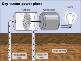
Geothermal power plants are categorized as the following:[3]
- Dry Steam – harnesses steam produced naturally in the geothermal reservoir
- Simplest and oldest
Image Source: U.S. Department of Energy
- Flash Steam – converts high-pressure hot groundwater to steam
- Most common
Image Source: U.S. Department of Energy
- Binary – uses geothermal hot water as the heat source to turn a secondary liquid to steam
- Most recent design
Image Source: U.S. Department of Energy
The market for dry steam plants is estimated to grow by 8.4% CAGR to US $2.4 billion by year’s end 2027. Binary plants will have a projected 8.8% CAGR. The flash steam segment is expected to see a 10.6% CAGR propelled by growth in the USA, Canada, Japan, China, and Europe, developing from an estimated US $2.1 billion regional market share in 2020 to US $4.3 billion in 2027, with China growing at the fastest rate. Asia-Pacific leaders for the flash steam sector will include Australia, India, and South Korea (US $1 billion regional forecast for 2027).[1]
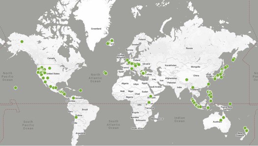
At the end of 2020 there were 522 geothermal plants operating worldwide.[4] As of 2019 there were 43 operating geothermal plants in California with the highest percentage in the Geysers complex north of San Francisco.[5] California has two proposed sites: Hell’s Kitchen (2023) and Casa Diablo IV (2021).[6] After California, Nevada is the second largest geothermal producing state in the U.S.
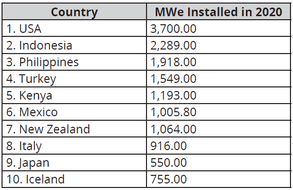
The table below shows the top ten nations for installed geothermal power generation in 2020.[7]
Top States in the United States for Geothermal Power Generation[8]

ThinkGeoEnergy’s Global Geothermal Power Plant Map[9]
A Transparency Market Research (TMR) report indicates a promising decade ahead for geothermal power, thanks to changes in attitudes about fossil fuels and an increasing focus on renewable energy, even among governments. The quest to reduce carbon footprints has become an encouragement for companies to fall back on geothermal energy. Despite the challenges to attracting investors due to high initial investments and delayed ROI, TMR expects the value of geothermal power equipment to steadily grow to approximately US $32 billion by year’s end 2027.[10]
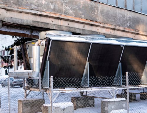
The steam and/or hot water from geothermal wells are high in corrosive elements such as chlorine, hydrogen sulfide, sulfuric acid, carbonic acid, and ammonia. The presence of these elements leads to the following types of corrosion within a plant: uniform corrosion, pitting corrosion, stress corrosion cracking, and sulphur stress corrosion cracking. Hydrogen bubbling and scale formation can also occur. Common types of scale in a geothermal system are calcium carbonate, heavy metal sulphides, and silica or metal-silicates. Corrosive elements in the steam and/or hot water attack the surfaces of the production and injection well casings, steam turbine flow path, and heat exchangers for binary systems. The corrosive gases emitting from the steam/hot water attack the infrastructure (steel and concrete), the external surfaces of machinery, and the electrical control systems (e.g., control panels, junction boxes, motor control centers, and motors). The following materials and methods are suggested to minimize the impact of these harsh geothermal conditions.
Prevention of Scale and Corrosion in Well and Turbine:
- Inject scale and corrosion inhibitor into the production well
- Inject scale and corrosion inhibitor into the discharge from the steam turbine
- Coat turbine blades and casing internals with VpCI®-396 Carbide
- Use S-15
Protection of Operational Systems:
- Lubrication systems
- Add M-528, M-530, M-531 at 2%-5% by weight
- Electronics/electricals
- Install Emitters
- VpCI®-101 Device, VpCI®-105 Emitter, VpCI®-111 Emitter, VpCI®-308 Pouch
- Apply ElectriCorr™ VpCI®-239
- Install Emitters
- Threaded assemblies such as valve stems and packing body bolts
- Apply VpCI® Super Penetrant
- Exposed machined surfaces
- Coat with VpCI®-391 or EcoShield® 386 Clear
- External painted surfaces – choose from the following coatings:
- VpCI®-386 HT for turbines and other equipment that reach 750 °F (399 °C)
- VpCI®-371 for surfaces that reach 1250 °F (677 °C)
- VpCI®-386, VpCI®-387, VpCI®-384, VpCI®-375 for non-submerged external surfaces below 350 °F (177 °C)
- To optimize coating selection, it is recommended that a sample of any fluid that will be in contact with the surface be sent to Cortec® lab for analysis
- Under insulation
- Apply VpCI®-658, VpCI®-619
- Transformer oil
- Add M-236
- Generators
- Place VpCI®-308 Pouch inside generator housing
- Steam system
- Inject Corrosorber® liquid into the production steam at the wellhead
- Dose rate to be calculated by Cortec® lab based on CO2 and H2S content
- Cooling water system
- Inject Corrosorber® liquid and VpCI®-647 into the condenser hotwell.
- Dose rate to be calculated by Cortec® lab based on CO2 and H2S content
- Inject Corrosorber® liquid and VpCI®-647 into the condenser hotwell.
- Inject Corrosorber® liquid into the production steam at the wellhead
Equipment Shutdown and Layup:
- Turbines
- Steam side
- Fog with VpCI®-337 at 3-0.5 oz./ft3 (0.31-0.52 L/m3)
- Oil side (if M-528, M-530, M-531 is not used during operation)
- Fog bearing housings, supply and drain lines, and oil sump with M-528, M-530, M-531 at 0.3-0.5 oz./ft3 (0.31-0.52 L/m3)
- Generators
- Oil side (if M-528, M-530, M-531 is not used during operation)
- Fog bearing housings, supply and drain lines, and oil sump with M-528, M-530, M-531 at 0.3-0.5 oz./ft3 (0.31 -0.52 L/m3)
- Electrical side
- Spray all electrical contacts with ElectriCorr™ VpCI®-239
- Install appropriate emitters in junction boxes, control panels, enclosures, and generator housing
- Switchgear
- Remove any rust with VpCI®-422 or VpCI®-423, followed by VpCI®-414
- Prime all surfaces to be painted with CorrVerter® Rust Converter Primer
- Topcoat with VpCI®-396
- Spray all contacts with ElectriCorr™ VpCI®-239
- Install appropriate emitter
- Transformers
- Remove any rust with VpCI®-422 or VpCI®-423, followed by VpCI®-414
- Apply CorrVerter® Rust Converter Primer to all surfaces that will be painted
- Topcoat with EcoShield® 386
- Spray all contacts with ElectriCorr™ VpCI®-239
- Install appropriate emitter
- Pumps (excluding oil)
- Flow path
- Fog with VpCI®-337 at 0.3-0.5 oz./ft3 (0.31-0.52 L/m3)
- Oil side (if M-528, M-530, M-531 is not used during operation)
- Fog bearing housings, supply and drain lines, and oil sump with M-528, M-530, or M-531 at 0.3-0.5 oz./ft3 (0.31-0.52 L/m3)
- Pumps (oil)
- Flow path
- Fog with M-528, M-530, or M-531 at 0.3-0.5 oz./ft3 (0.31-0.52 L/m3)
- Oil side (if M-529 is not used during operation)
- Fog bearing housings, supply and drain lines, and oil sump with M-528, M-530, or M-531 at 0.3-0.5 oz./ft3 (0.31-0.52 L/m3)
- Piping (oil)
- Fog with M-528, M-530, or M-531 at 0.3-0.5 oz./ft3 (0.31-0.52 L/m3)
- Piping (non-oil)
- Fog with VpCI®-337 at 0.3-0.5 oz./ft3 (0.31-0.52 L/m3)
- Cooling water system
- Option 1:
- Set up jumper system between condensate injection and condensate inlet to condenser
- Add between 0.3-1.0% by weight VpCI®-649 to the condensate and circulate for 24 hours
- Drain or leave wet
- If system is drained, place Cooling Tower Frog® water soluble bags in the designated cooling water components
- Option 2:
- Set up jumper system between condensate injection and condensate inlet to condenser
- Fog with VpCI®-337 at 0.3-0.5 oz./ft3 (0.31-0.52 L/m3) into the condenser and all pumps and piping
- It may be necessary to isolate certain parts of the system and create a small pressure drop to increase the travel of the VpCI®-337
- Option 1:
- Flow path
- Flow path
- Oil side (if M-528, M-530, M-531 is not used during operation)
- Steam side
General Maintenance and Repair:
- Clean all rusted exterior surfaces with either VpCI®-423 or VpCI®-422
- Neutralize with a 10% solution of VpCI®-414
- Clean all exposed machined surfaces with a 10% solution of VpCI®-414
- Coat with VpCI®-391
- Spray all threaded assemblies such as valve stems, packing body bolts, and fasteners with VpCI® Super Penetrant
- Repair any painted surfaces with the appropriate Cortec® coating
CASE HISTORIES
Preservation of Instrumentation and Electricals in H2S Conditions

<https://www.corteccasehistories.com/?s2member_file_download=access-s2member-level1/ch712.pdf>.
References
- Research and Markets.com. “Geothermal Energy – Global Market Trajectory & Analytics.” Report Description. April 2021. <https://www.researchandmarkets.com/reports/1382342/geothermal_energy_global_market_trajectory_and#relb0-5139915>.
- S. Energy Information Administration. “Geothermal explained: Geothermal power plants.” 19 November 2020 <https://www.eia.gov/energyexplained/geothermal/geothermal-power-plants.php>.
- Clean Energy Ideas. “Geothermal Power Plants.” 19 September 2018 <https://www.clean-energy-ideas.com/geothermal/geothermal-power/geothermal-power-plant/>.
- Richter, Alexander. “ThinkGeoEnergy Global Geothermal Power Plant Map – updated.” ThinkGeoEnergy.com. 23 November 2020 <https://www.thinkgeoenergy.com/thinkgeoenergy-global-geothermal-power-plant-map-updated/>.
- California Energy Commission. “California Geothermal Energy Statistics and Data.” Energy.CA.gov. 2019. <https://ww2.energy.ca.gov/almanac/renewables_data/geothermal/index_cms.php>.
- “List of geothermal power stations in the United States.” 25 January 2021. <https://en.wikipedia.org/wiki/List_of_geothermal_power_stations_in_the_United_States>.
- Huttrer, Gerald W. “Geothermal Power Generation in the World 2015-2020 Update Report.” Proceedings of World Geothermal Congress 2020. Reykjavik, Iceland. 2 May 2020. Geothermal-Energy.org. <https://www.geothermal-energy.org/pdf/IGAstandard/WGC/2020/01017.pdf>.
- Sen Nag, Oishimaya, Ph.D. “US States With The Highest Geothermal Capacity.” WorldAtlas. 24 May 2020. <https://www.worldatlas.com/articles/us-states-with-the-highest-geothermal-capacity.html>.
- com. Global Geothermal Power Plant Map. 2021 <https://www.thinkgeoenergy.com/map/>.
- Transparency Market Research. “Analysis of Potential Impact of COVID-19 on Geothermal Power Equipment Market.” Published on SBWire.com. 12 April 2021. <http://www.sbwire.com/press-releases/geothermal-power-equipment-mar/release-1335302.htm>.
For a PDF version please click here.